Almost all of you have seen or used an automated drinks maker, so I presume you have a rough idea on what is an automated drink maker.
Please note that this project was my degree 2nd year group project , at Northumbria University. Even though the steps outlined below, will have sufficient information to build your own drink maker, I highly suggest you make your own or tweak this design. Electronics/Software-wise, the project is working 100%, but the mechanical mechanisms needs some serious rework.
PLEASE NOTE ALSO THAT I WILL BE ONLY EXPLAINING THE SOFTWARE PART OF THE PROJECT, AS THAT WAS MY ROLE. ATTACHED ARE THE REPORTS, WHICH INCLUDES EVERYTHING NEEDED TO MAKE THE PROJECT.ATTACHMENT: PRELIMINARY REPORT, INTERMEDIATE REPORT(this document has the most detailed information on building the whole system, but is with a group member of mine. Once he mails me the report, i will post it here. Sorry!),
FINAL REPORTOk, before I start, I presume you have decent soldering skills, basic PIC Microcontroller background, and also basic mechanical construction knowledge.
If you already dont have a PIC16F877A microcontroller and a PIC Programmer, please obtain these two.
The PIC16F877A can be sampled for free at
http://sample.microchip.comIf you don't have a PIC Programmer, i suggest making this simple one which I have been using till now:
http://feng3.cool.ne.jp/en/pg5v2.htmlI used MikroBasic v4.0.0.3 to code my PIC, and EAGLE to design the PCBs.
1st, lets go through the basic operation of the drinks maker.
- The PIC acts as the brain, controlling every aspect of the drink maker.
- There are 5 slots in the drink maker, 1 for sugar, 1 for milk, 1 for hot water, and the other 2 depends on the user (eg: coffee, milo etc..)
-Once the drink maker is powered on, nothing happens until the water heater has heated up, and there is a cup present in the cup holder.
-After this, you are free to choose a preset of drinks, make your own drink, or save your own drinks.
Ok, since we have got that out of the way, lets 1st look at all the sub components of the project:
- PIC microcontroller board
- Motor driver board
- Power Supply board
- Cup Sensor board
So, the mechanical construction uses normal DC motors to release the ingredients (ex: sugar). So, lets say you would want a tablespoon of sugar, the motor is rotated in one direction for a period of time, and rotated in another direction back to its initial position. For 2 tablespoons, the above steps are done twice, and so on for more tablespoons.
A Motor controller, BA6208 (
Datasheet) is used, as it can control a motor to rotate both ways. The motor controller expects a high in Ain to rotate 1 direction and a high in Bin to reverse. A high in Ain and Bin results in the motor braking. Aout and Bout are the outputs to the motor.
Thus, only logic 1(high) needs to be sent to the motor driver, and a active-high switch is used.
Ok, now back to the software. The software is nothing more then a menu system. As of such, the software can be modified to be used as a menu system for any application. Just be creative.
Here is the Block Diagrams of the operation of the software. There are only 2 buttons to operate the menu: GO and SELECT. The 3rd button, RESET is wired to MCLR pin of the PIC16F877A and resets the whole system (retaining any eeprom data saved).
Main Menu:
Shown above is the main menu structure of the program. Before entering the main menu itself, the program will ask the user to place the cup, and is he/she has done that, it will wait until the water has been heated.Once entered the main menu, the GO button will go to the next menu and the SELECT button will enter the selected menu. Below, is the flowchart for the three sub-menus; Preset Mode, Manual Mode, and Memory Mode.
Preset Mode: 
Once entered the Preset Mode, the GO button will advance to the next sub-menu and the SELECT button will enter the selected menu. Once entered either to Hot chocolate or Coffee, there is a conditional branch. The program will make the drink if the GO button is pressed or it will cancel the drink if the SELECT button is pressed.
Manual Mode:
Upon entering the Manual Mode menu, you will be asked to choose the number of tablespoons of hot chocolate. In this menu, the GO button will increase the number of tablespoon by 1 and the SELECT button will go to the next item. After you have chosen all the items, you will be asked to choose whether you want to make a drink or cancel the drink. GO will make the drink and SELECT will cancel the drink.
Memory Mode:
The Memory mode has two sub-menus, that is Make drink from memory and Save drink to memory. As usual, the GO button will go to the next button and the SELECT button will enter the menu. Once entered the Save drink to memory menu, the user will be asked to choose the amount of ingredients. This procedure is exactly the same as manual mode, the only exception being once you’ve finished, the user will be asked to save the drink or cancel. GO will save the drink and SELECT will cancel the drink. Once entered the Make drink from memory menu, GO will select between the 2 user memory locations and select will make the drink.
By looking through the block diagrams, I hope you understand how the menu system works.
Get the source code
HERE, and the hex file
HERE.
MCU Board Schematic:

MCU Board PCB Design:

Get the Schematic
HERE and PCB Design
HERE.
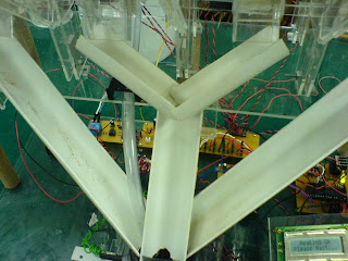
Pics of the final product:


Please feel free to contact me should you have anything to ask.


 Once entered the Preset Mode, the GO button will advance to the next sub-menu and the SELECT button will enter the selected menu. Once entered either to Hot chocolate or Coffee, there is a conditional branch. The program will make the drink if the GO button is pressed or it will cancel the drink if the SELECT button is pressed.
 The Memory mode has two sub-menus, that is Make drink from memory and Save drink to memory. As usual, the GO button will go to the next button and the SELECT button will enter the menu. Once entered the Save drink to memory menu, the user will be asked to choose the amount of ingredients. This procedure is exactly the same as manual mode, the only exception being once you’ve finished, the user will be asked to save the drink or cancel. GO will save the drink and SELECT will cancel the drink. Once entered the Make drink from memory menu, GO will select between the 2 user memory locations and select will make the drink.


 Dont be fooled by their cute look, these gals are devils!
.jpg) Catch of the day!
Catch of the day! My friend with his catch
.jpg) The location: Byram, Nibong Tebal
The location: Byram, Nibong Tebal.jpg) The location: Byram, Nibong Tebal
The location: Byram, Nibong Tebal.jpg) The location: Byram, Nibong Tebal
The location: Byram, Nibong Tebal

 After you have completed this, please remember to Heat Sink ALL the LM317Ts. If not they WILL overheat and shut down.


 EAGLE Schematic and PCB Design: Schematic, PCB
 Both boards done, and fan controller fixed to perspex( note that i have used fibre optic cable to route the light from the leds to the panel, that way you get a neat 1mm display of each led, and not the bulky 5mm leds):


..JPG)
..JPG)
..JPG)
..JPG)


..JPG)

..JPG)


..JPG)
